Facts Theory
Chapter 1:- FACTS Concepts and general system consideration
Q.1) State the importance of use of FACTS devices in power transmission.
Give suitable example.
Answer:-
Following are the importance of use of FACTS devices in power transmission;
- The FACTS Controllers has the ability to control the interrelated parameters that govern the operation of transmission systems including series impedance, shunt impedance, current, voltage, phase angle, and the damping of oscillations at various frequencies below the rated frequency.
- These constraints cannot be overcome, while maintaining the required system reliability, by mechanical means without lowering the useable transmission capacity. Whereas FACTS Controllers can enable a line to carry power closer to its thermal rating.
- FACTS technology opens up new opportunities for controlling power and enhancing the usable capacity of present, as well as new and upgraded, lines.
- The possibility that current through a line can be controlled at a reasonable cost.
- Boost the voltage of existing lines.
- Enable corresponding power to flow through such lines under normal and contingency conditions.
- Enabling utilities to get the most service from their transmission facilities and enhance grid reliability.
- The FACTS technology is not a single high-power Controller, but rather a collection of controllers, which can be applied individually or in coordination with others to control one or more of the interrelated system parameters.
Q.2) What is loading capability of transmission line ?
Explain in the limits of loading capacity of transmission line.
Answer:-
The best use of the transmission asset, and to maximize the loading capability (taking into account contingency conditions),
What limits the loading capability, and what can be done about it? Basically, there are three kinds of limitations:
- Thermal
- Dielectric
- Stability
Thermal capability of an overhead line is a function of the ambient temperature, wind conditions, condition of the conductor, and ground clearance. It varies perhaps by a factor of 2 to 1 due to the variable environment and the loading history. The nominal rating of a line is generally decided on a conservative basis, envisioning a statistically worst ambient environment case scenario. Yet this scenario occurs but rarely which means that in reality, most of the time, there is a lot more real time capacity than assumed. Some utilities assign winter and summer ratings, yet this still leaves a considerable margin to play with. There are also off-line computer programs that can calculate a line's loading capability based on available ambient environment and recent loading history. Then there are the on-line monitoring devices that provide a basis for on-line real-time loading capability. Sometimes, the ambient conditions can actually be worse than assumed, and having the means to determine actual rating of the line could be useful. During planning/design stages, normal loading of the lines is frequently decided on a loss evaluation basis under assumptions which may have changed for a variety of reasons; however losses can be taken into account on the real-time value basis of extra loading capability.Off-line and on-line loading capability monitors can also be used to obtain real time loading capability of transformers. The transformer also lends itself to enhanced
cooling. Then there is the possibility of upgrading a line by changing the conductor to that of a higher current rating, which may in turn require structural upgrading. The FACTS technology can help in making an effective use of this newfound capacity.
From an insulation point of view, many lines are designed very conservatively. For a given nominal voltage rating, it is often possible to increase normal operation by +10% voltage (i.e., 500 kV-550 kV) or even higher. Care is then needed to ensure that dynamic and transient over voltages are within limits. Modern gapless arresters, or line insulators with internal gapless arresters, or powerful thyristor-controlled overvoltage suppressors at the substations can enable significant increase in the line and substation voltage capability. The FACTS technology could be used to ensure acceptable over-voltage and power flow conditions.
There are a number of stability issues that limit the transmission capability.
These include:
- Transient stability
- Dynamic stability
- Steady-state stability
- Frequency collapse
- Voltage collapse
- Subsynchronous resonance
Q.3) From first principle derive power flow equation, 𝑷 = E1E2 𝒔𝒊𝒏𝜹
𝑿
Figure (a) shows a simplified case of power flow on a transmission line. Locations 1 and 2 could be any transmission substations connected by a transmission line. Substations may have loads, generation, or may be interconnecting points on the system and for simplicity they are assumed to be stiff busses. E1 and E2 are the magnitudes of the bus voltages with an angle δ between the two.
The line is assumed to have inductive impedance X, and the line resistance and capacitance are ignored. As shown in the phasor diagram [Figure (b)] the driving voltage drop in the line is the phasor difference EL between the two line voltage phasors, E1 and E2.
The line current magnitude is given by,
Figure (b) shows that the current flow phasor is perpendicular to the driving voltage (90° phase lag). If the angle between the two bus voltages is small, the current flow largely represents the active power. Increasing or decreasing the inductive impedance of a line will greatly affect the active power flow.
Figure (c), corresponding to Figure (b), shows a phasor diagram of the relationship between the active and reactive currents with reference to the voltages at the two ends.


Q.4) How FACTS controllers are classified? Explain in brief.
OR
Q.4) What is FACTS controller? Clarify distinguish between FACTS controllers with each other.
Answer:-
FACTS Controller:-
A power electronic-based system and other static equipment that provide control of one or more AC transmission system parameters.
In general, FACTS Controllers can be divided into four categories:
- Series Controllers
- Shunt Controllers
- Combined series-series Controllers
- Combined series-shunt Controllers
Figure (a) shows the general symbol for a FACTS Controller: a thyristor arrow inside a box.
- Series Controllers: [Figure (b)]
The series Controller could be variable impedance, such as capacitor, reactor, etc., or power electronics based variable source of main frequency, subsynchronous and harmonic frequencies (or a combination) to serve the desired need. In principle, all series Controllers inject voltage in series with the line. Even a variable impedance multiplied by the current flow through it, represents an injected series voltage in the line. As long as the voltage is in phase quadrature with the line current, the series Controller only supplies or consumes variable reactive power. Any other phase relationship will involve handling of real power as well.
- Shunt Controllers: [Figure (c)]
As in the case of series Controllers, the shunt Controllers may be variable impedance, variable source, or a combination of these. In principle, all shunt Controllers inject current into the system at the point of connection.
Even a variable shunt impedance connected to the line voltage causes a variable current flow and hence represents injection of current into the line. As long as the injected current is in phase quadrature with the line voltage, the shunt Controller only supplies or consumes variable reactive power. Any other phase relationship will involve handling of real power as well.
- Combined series-series Controllers: [Figure (d)]
This could be a combination of separate series controllers, which are controlled in a coordinated manner, in a multiline transmission system. Or it could be a unified Controller, Figure (d), in which series Controllers provide independent series reactive compensation for each line but also transfer real power among the lines via the power link. The real power transfer capability of the unified series-series Controller, referred to as Interline Power Flow Controller, makes it possible to balance both the real and reactive power flow in the lines and thereby maximize the utilization of the transmission system. Note that the term "unified" here means that the de terminals of all Controller converters are all connected together for real power transfer.
- Combined series-shunt Controllers: [Figures (e) and (f)]
This could be a combination of separate shunt and series Controllers, which are controlled in a coordinated manner [Figure (e)], or a Unified Power Flow Controller with series and shunt elements [Figure (f)]. In principle, combined shunt and series Controllers inject current into the system with the shunt part of the Controller and voltage in series in the line with the series part of the Controller. However, when the shunt and series Controllers are unified, there can be a real power exchange between the series and shunt Controllers via the power link.


CHAPTER 3: STATIC SHUNT COMPENSATOR
Q.1) Explain with neat vector diagram, how transient stability improves with ideal midpoint compensators.
OR
Q.1) Explain how stability margin is increased when shunt compensator is used for transmission line.
Answer:-

Consider the simple two-machine (two-bus) transmission model in which an ideal VAr compensator is shunt connected at the midpoint of the transmission line, as shown in Figure (a). For simplicity, the line is represented by the series line inductance. The compensator is represented by a sinusoidal ac voltage source (of the fundamental frequency), in-phase with the midpoint voltage, Vm and with an amplitude identical to that of the sending- and receiving-end voltages (Vm = Vs = Vr = V) The midpoint compensator in effect segments the transmission line into two independent parts: the first segment, with an impedance of X/2, carries power from the sending end to the midpoint, and the second segment, also with an impedance of X/2, carries power from the midpoint to the receiving end. The relationship between voltages, Vm, Vs and Vr (together with Vsm and Vrm )and line segment currents Ism and Irm, is shown by the phasor diagram in Figure (b). Note that the midpoint VAr compensator exchanges only reactive power with the transmission line in this process. For the lossless system assumed, the real power is the same at each terminal (sending end, midpoint, and receiving end) of the line, and it can be derived readily from the phasor diagram of Fig. (b). With

the transmitted power is
The relationship between real power P, reactive power Q, and angle δ for the case of ideal shunt compensation is shown plotted in Figure (c). It can be observed that the midpoint shunt compensation can significantly increase the transmittable power (doubling its maximum value) at the expense of a rapidly increasing reactive power demand on the midpoint compensator (and also on the end-generators). It is also evident that for the single-line system of Figure the midpoint of the transmission line is the best location for the compensator. This is because the voltage sag along the uncompensated transmission line is the largest at the midpoint. Also, the compensation at the midpoint breaks the transmission line into two equal segments for each of which the maximum transmittable power is the same. For unequal segments, the transmittable power of the longer segment would clearly determine the overall transmission limit.

The concept of transmission line segmentation can be expanded to the use of multiple compensators, located at equal segments of the transmission line, as illustrated for four line segments in Figure above Theoretically, the transmittable power would double with each doubling of the segments for the same overall line length. Furthermore, with the increase of the number of segments, the voltage variation along the line would rapidly decrease, approaching the ideal case of constant voltage profile.
How stability margin improves?
Reactive shunt compensation can significantly increase the maximum transmittable power. Thus, it is reasonable to expect that, with suitable and fast controls, shunt compensation will be able to change the power flow in the system during and following dynamic disturbances so as to increase the transient stability limit and provide effective power oscillation damping.
The meaning of the equal area criterion is explained with the aid of the simple two machine (the receiving end is an infinite bus), two line system shown in Figure (a) and the corresponding P versus δ curves shown in Figure (b).
Assume that the complete system is characterized by the P versus δ curve "a" and is operating at angle δ1 to transmit power P1 when a fault occurs at line segment "1". During the fault the system is characterized by the P versus δ curve "b" and thus, over this period, the transmitted electric power decreases significantly while mechanical input power to the sending- end generator remains substantially constant corresponding to P1; As a result, the generator accelerates and the transmission angle increases from δ1 to δ2 at which the protective breakers disconnect the faulted line segment "1" and the sending-end generator 'absorbs accelerating energy, represented by area "A1" After fault clearing, without line segment "1" the degraded system is characterized by the P versus δ curve "c." At angle δ2 on curve "c" the transmitted power exceeds the mechanical input power P1 and the sending end generator starts to decelerate; however, angle Bfurther increases due to the kinetic energy stored in the machine. The maximum angle reached at δ3, where the decelerating energy, represented by area "A2" becomes equal to the accelerating energy represented by area "A1". The limit of transient stability is reached at δ3 = δcrit, beyond which the decelerating energy would not balance the accelerating energy and synchronism between the sending end and receiving end could not be restored. The area "Amargin," between δ3 and δcrit represent the transient stability margin of the system.

Comparison of Figures (a) and (b) clearly shows a substantial increase in the transient stability margin the ideal midpoint compensation with unconstrained VAr output can provide by the effective segmentation of the transmission line. Alternatively, if the uncompensated system has a sufficient transient stability margin, shunt compensation can considerably increase the transmittable power without decreasing this margin.
Q.2) Explain effect of use of shunt compensators on receiving end voltage stability.
Answer:-
The midpoint voltage support of a two-machine transmission power system discussed above can easily extend to the more special case of radial transmission. Indeed, if a passive load, consuming power P at voltage Vr is connected to the midpoint in place of the receiving-end part of the system (which comprises the receiving-end generator and transmission link X/2), the sending-end generator with the X/2 impedance and load would represent a simple radial system.
Clearly, without compensation the voltage at the midpoint (which is now the receiving end) would vary with the load (and load power factor).
A simple radial system with feeder line reactance of X and load impedance Z, is shown in Figure
(a) together with the normalized terminal voltage Vr versus power P plot at various load power factors, ranging from 0.8 lag and 0.9 lead. The "nose-point" at each plot given for a specific power factor represents the voltage instability corresponding to that system condition. It should be noted that the voltage stability limit decreases with inductive loads and increases with capacitive loads. The inherent circuit characteristics of the simple radial structure, and the Vr
versus P plots shown, clearly indicate that shunt reactive compensation can effectively increase the voltage stability limit by supplying the reactive load and regulating the terminal voltage (V - Vr = 0) as illustrated in Figure (b). It is evident that for a radial line, the end of the line, where the largest voltage variation is experienced, is the best location for the compensator. (Recall that, by contrast, the midpoint is the most effective location for the line interconnecting two ac system buses.) Reactive shunt compensation is often used in practical applications to regulate the voltage at a given bus against load variations, or to provide voltage support for the load when, due to generation or line outages, the capacity of the sending-end system becomes impaired. A frequently encountered example is when a large load area is supplied from two or more generation plants with independent transmission lines. (This frequently happens when the locally generated power becomes inadequate to supply a growing load area and additional power is imported over a separate transmission link.) The loss of one of the power sources could suddenly increase the load demand on the remaining part of the system, causing severe voltage depression that could result in an ultimate voltage collapse.
Q.3) State the requirements of good shunt compensators.
Answer:-
The functional requirements of reactive shunt compensators used for increased power transmission, improved voltage and transient stability, and power oscillation damping can be summarized as follows:
- The compensator must stay in synchronous operation with the ac system at the compensated bus under all operating conditions including major disturbances. Should the bus voltage be lost temporarily due to nearby faults, the compensator must be able to recapture synchronism immediately at fault clearing.
- The compensator must be able to regulate the bus voltage for voltage support and improved transient stability, or control it for power oscillation damping and transient stability enhancement, on a priority basis as system conditions may require.
- For a transmission line connecting two systems, the best location for VAr compensation is in the middle, whereas for a radial feed to a load the best location is at the load end.
Q.4) Explain the working principle of TSC in shunt compensation.
OR
Q.4) Differentiate between TCR and TSC compensators based on working conditions, operating V-I area, harmonics/ transients. Also draw neat diagram of TSC and TCR.
TCR
A. Working conditions:-
An elementary single-phase thyristor-controlled reactor (TCR) is shown in Figure (a). It consists of a fixed (usually air-core) reactor of inductance L, and a bidirectional thyristor valve (or switch) sw. Currently available large thyristors can block voltage up to 4000 to 9000 volts and conduct current up to 3000 to 6000 amperes. Thus, in a practical valve many thyristors (typically 10 to 20) are connected in series to meet the required blocking voltage levels at a given power rating. A thyristor valve can be brought into conduction by simultaneous application of a gate pulse to all thyristors of the same polarity. The valve will automatically block immediately after the ac current crosses zero, unless the gate signal is reapplied. The current in the reactor can be controlled from maximum (thyristor valve closed) to zero (thyristor valve open) by the method offiring delay angle control.
TCR
B. Operating V-I area:-
It is clear from working condition that the TCR can control the fundamental current continuously from zero (valve open) to a maximum (valve closed) as if it was a variable reactive admittance. Thus, an effective reactive admittance, BL(α), for the TCR can be defined. This admittance, as a function of angle a, can be written directly from

Evidently, the admittance BL(α) varies with a in the same manner as the fundamental current ILF(α). The each delay angle a an effective admittance BL(α) can be defined which determines the magnitude of the fundamental current, ILF(α) in the TCR at a given applied voltage V. In practice, the maximal magnitude of the applied voltage and that of the corresponding current will be limited by the ratings of the power components (reactor and thyristor valve) used. Thus, a practical TCR can be operated anywhere in a defined V-I area, the boundaries of which are determined by its maximum attainable admittance, voltage, and current ratings, as illustrated in Figure above.
C. Harmonics/ Transients:-
The thyristor-controlled reactor, in addition to the wanted fundamental current, also generates harmonics. For identical positive and negative current half-cycles, only odd harmonics are generated. The amplitudes of these are a function of angle a, as expressed by the following equation:
The amplitude variation of the harmonics, expressed as percent of the maximum fundamental current, is shown plotted against α in Figure. In a three-phase system, three single-phase thyristor-controlled reactors are used, usually in delta connection. Under balanced conditions, the triple-n harmonic currents (3rd, 9th, 15th, etc.) circulate in the delta connected TCRs and do not enter the power system. The magnitudes of the other harmonics generated by the thyristor- controlled reactors can be reduced by various methods.
TSC
A. Working conditions:-
A single-phase thyristors switched capacitor (TSC) is shown in Figure (a). It consists of a capacitor, a bidirectional thyristor valve, and a relatively small surge current limiting reactor. This reactor is needed primarily to limit the surge current in the thyristor valve under abnormal operating conditions (e.g., control malfunction causing capacitor switching at a "wrong time," when transient free switching conditions are not satisfied); it may also be used to avoid resonances with the ac system impedance at particular frequencies. Under steady-state conditions, when the thyristor valve is closed and the TSC branch is connected to a sinusoidal ac voltage source, v = V sin on, the current in the branch is given by
B. Operating V-I area:-
The TSC branch represents a single capacitive admittance which is either connected to, or disconnected from the ac system. The current in the TSC branch varies linearly with the applied voltage according to the admittance of the capacitor as illustrated by the V-I plot in Figure. The maximum applicable voltage and the corresponding current are limited by the ratings of the TSC components.
C. HARMONIC/TRANSIENTS:
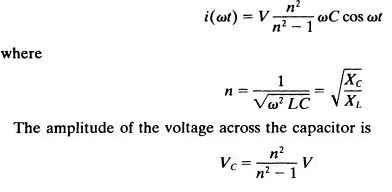
If the voltage across the disconnected capacitor remained unchanged, the TSC bank could be switched in again, without any transient, at the appropriate peak of the applied ac voltage, Normally, the capacitor bank is discharged after disconnection. Thus, the reconnection of the capacitor may have to be executed at some residual capacitor voltage between zero and V n 2/(n 2- 1). This can be accomplished with the minimum possible transient disturbance if the thyristor valve is turned on at those instants at which the capacitor residual voltage and the applied ac voltage are equal, that is, when the voltage across the thyristor valve is zero as shown in Figure below,
Q.5) Draw and explain losses versus VAr-output characteristics of FC-TCR.
Answer:-
A basic VAr generator arrangement using a fixed (permanently connected) capacitor with a thyristor-controlled reactor (FC-TCR) is shown functionally in Figure (a). The current in the reactor is varied by the previously discussed method of firing delay angle control. The fixed capacitor in practice is usually substituted, fully or partially, by a filter network that has the necessary capacitive impedance at the fundamental frequency to generate the reactive power required, but it provides a low impedance at selected frequencies to shunt the dominant harmonics produced by the TCR.

The fixed capacitor, thyristor-controlled reactor type VAr generator may be considered essentially to consist of a variable reactor (controlled by delay angle a) and a fixed capacitor, with an overall VAr demand versus VAr output characteristic as shown in Figure (b). As seen, the constant capacitive VAr generation (Qc) of the fixed capacitor is opposed by the variable VAr absorption (QL) of the thyristor-controlled reactor, to yield the total VAr output (Q) required. At the maximum capacitive VAr output, the thyristor-controlled reactor is off (a = 90°). To decrease the capacitive output, the current in the reactor is increased by decreasing delay angle a. At zero VAr output, the capacitive and inductive currents become equal and thus the capacitive and inductive VArs cancel out.
The control of the thyristor-controlled reactor in the FC-TCR type VAr generator needs to provide four basic functions, as shown in Figure (a).
One function is synchronous timing. This function is usually provided by a phase locked loop circuit that runs in synchronism with the ac system voltage and generates appropriate timing pulses with respect to the peak of that voltage. (In a different approach, the ac voltage itself may be used for timing. However, this seemingly simple approach presents difficult problems during system faults and major disturbances when the voltage exhibits wild fluctuations and large distortion.)
The second function is the reactive current (or admittance) to firing angle conversion. This can be provided by a real time circuit implementation of the mathematical relationship between the amplitude of the fundamental TCR current ILF(α) and the delay angle a. Several circuit approaches are possible. One is an analog function generator producing in each half-cycle a scaled electrical signal that represents the ILF(α) versus a relationship. [This approach is illustrated in Figure (b).
Another is a digital "look-up table" for the normalized ILF(α) versus a function which is read at regular intervals (e.g., at each degree) starting from α = 0 (peak of the voltage) until the requested value is found, at which instant a firing pulse is initiated. A third approach is to use a microprocessor and compute, prior to the earliest firing angle (α = 0), the delay angle corresponding to the required ILF(α). The actual firing instant is then determined simply by a timing circuit (e.g., a counter) "measuring" a from the peak of the voltage.
The third function is the computation of the required fundamental reactor current IFL, from the requested total output current IQ (sum of the fixed capacitor and the TCR currents) defined by the amplitude reference input IQRef to the VAr generator control. This is simply done by subtracting the (scaled) amplitude of the capacitor current, Ic from IQRef (Positive polarity for IQRef means inductive output current, and negative polarity means capacitive output current).
The fourth function is the thyristor firing pulse generation. This is accomplished by the firing pulse generator (or gate drive) circuit which produces the necessary gate current pulse for the thyristors to turn on in response to the output signal provided by the reactive current to firing angle converter. In order to provide sufficient insulation between the ground level control and the gate drive circuits, the gating information is usually transmitted via optical fibers ("light pipes"). The operation of the FC-TCR type VAr generator is illustrated by the waveforms in Figure (b).
This type of loss characteristic is advantageous when the average capacitive VAr output is relatively high as, for example, in industrial applications requiring power factor correction, and it is disadvantageous when the average VAr output is low, as for example, in the case of dynamic compensation of power transmission systems.
Q.6) Explain switching converter type VAr generators with basic operating principle and control approach.
OR
Q.6) Explain working of 3 ph-12 pulse converter used for generation of reactive power.
Answer:-
These (dc to ac or ac to ac) converters are operated as voltage and current sources and they produce reactive power essentially without reactive energy storage components. Their operation is similar to that of an ideal synchronous machine whose reactive power output is varied by excitation control. Like the mechanically powered machine, they can also exchange real power with the ac system. Because of these similarities with a rotating synchronous generator, they are termed Static Synchronous Generators (SSGs). When an SSG is operated without an energy source, and with appropriate controls to function as a shunt-connected reactive compensator, it is termed, analogously to the rotating synchronous compensator (condenser), a Static Synchronous Compensator (Condenser) or STATCOM (STATCON).
Controllable reactive power can be generated by all types of de to ac and ac to ac switching converters. The former group is generally called dc to ac converters or just converters, whereas the latter one is referred to as frequency changers or frequency converters or cycloconverters. The normal function of converters is to change dc power to ac and that of frequency changers to change ac power of one frequency to ac power of another frequency.
Operating principle:-
The basic principle of reactive power generation by a voltage-sourced converter is akin to that of the conventional rotating synchronous machine shown schematically in Figure. For purely reactive power flow, the three-phase induced electromotive forces (EMFs), ea, eb., and ec of the synchronous rotating machine are in phase with the system voltages, Va, Vb, and Vc.. The reactive current I drawn by the synchronous compensator is determined by the magnitude of the system voltage V, that of the internal voltage E, and the total circuit reactance (synchronous machine reactance plus transformer leakage reactance plus system short circuit reactance) X:
The corresponding reactive power Q exchanged can be expressed as follows:

By controlling the excitation of the machine, and hence the amplitude E of its internal voltage relative to the amplitude V of the system voltage, the reactive power flow can be controlled. Increasing E above V (i.e., operating over-excited) results in a leading current, that is, the machine is "seen" as a capacitor by the ac system. Decreasing E below V (i.e., operating under-excited) produces a lagging current, that is, the machine is "seen" as a reactor (inductor) by the ac system. Under either operating condition a small amount of real power of course flows from the ac system to the machine to supply its mechanical and electrical losses. Note that if the excitation of the machine is controlled so that the corresponding reactive output maintains or varies a specific parameter of the ac system (e.g., bus voltage), then the machine (rotating VAr generator) functions as a rotating synchronous compensator (condenser).

Figure:- Reactive power generation by rotating a voltage-sourced switching converter.
The basic voltage-sourced converter scheme for reactive power generation is shown schematically, in the form of a single-line diagram, in Figure. From a dc input voltage source, provided by the charged capacitor Cs, the converter produces a set of controllable three-phase output voltages with the frequency of the ac power system. Each output voltage is in phase with, and coupled to the corresponding ac system voltage via a relatively small (0.1-0.15 p.u.) tie reactance (which in practice is provided by the per phase leakage inductance of the coupling transformer). By varying the amplitude of the output voltages produced, the reactive power exchange between the converter and the ac system can be controlled in a manner similar to that of the rotating synchronous machine. That is, if the amplitude of the output voltage is increased above that of the ac system voltage, then the current flows through the tie reactance from the converter to the ac system, and the converter generates reactive (capacitive) power for the ac system. If the amplitude of the output voltage is decreased below that of the ac system, then the reactive current flows from the ac system to the converter, and the converter absorbs reactive (inductive) power. If the amplitude of the output voltage is equal to that of the ac system voltage, the reactive power exchange is zero.

The three-phase output voltage is generated by a voltage-sourced de to ac converter operated from an energy storage capacitor. All of the practical converters so far employed in actual transmission applications are composed of a number of elementary converters, that is, of single- phase H-bridges, or three-phase, two-level, six-pulse bridges, or three-phase, three-level, 12- pulse bridges, shown in Figure. The valves used in the elementary converters usually comprise a number (3 to 10) of series connected power semiconductors, e.g., GTO thyristors with reverse- parallel diodes. The operation of the voltage-sourced converter, used as a controllable static VAr generator, can be explained without considering the detailed operation of the converter valves by basic physical laws governing the relationship between the output and input powers. The key to this explanation resides in the physical fact that, like in all switching power converters, the net instantaneous power at the ac output terminals must always be equal to the net instantaneous power at the de input terminals (neglecting the losses in the semiconductor switches).
Since the converter supplies only reactive output power (its output voltages are controlled to be in phase with the ac system voltages), the real input power provided by the de source (charged capacitor) must be zero (as the total instantaneous power on the ac side is also zero). Furthermore, since reactive power at zero frequency (at the de capacitor) by definition is zero, the de capacitor plays no part in the reactive power generation. In other words, the converter simply interconnects the three ac terminals in such a way that the reactive output currents can flow freely between them.
Chapter 4 :- Static Series Compensators
Q.1) With a neat schematic diagram, explain series capacitive compensation (SCC).
OR
Q.1) What is series compensation? How it is obtained in transmission line.
Answer:-
The reactive shunt compensation is highly effective in maintaining the desired voltage profile along the transmission line interconnecting two busses of the ac system and providing support to the end voltage of radial lines in the face of increasing power demand. Thus, reactive shunt compensation, when applied at sufficiently close intervals along the line, could theoretically make it possible to transmit power up to thermal limit of the line, if a large enough angle between the two end voltages could be established. However, shunt compensation is ineffective in controlling the actual transmitted power which, at a defined transmission voltage, is ultimately determined by the series line impedance and the angle between the end voltages of line.
Controllable series line compensation is a cornerstone of FACTS technology. It can be applied to achieve full utilization of transmission assets by controlling the power flow in the lines, preventing loop flows and, with the use of fast controls, minimizing the effect of system disturbances, thereby reducing traditional stability margin requirements. The effect of series compensation on the basic factors, determining maximal power transmission, steady- state power transmission limit, transient stability, voltage stability and power oscillation damping, will be examined.
The basic idea behind series capacitive compensation is to decrease the overall effective series transmission impedance from the sending end to the receiving end, i.e., X in the P = (V2 / X) sinδ relationship characterizing the power transmission over a single line.
Consider the simple two-machine model, analogous to that shown for shunt compensation in Figure, but with a series capacitor compensated line, which, for convenience, is assumed to be composed of two identical segments, as illustrated in Figure (a). The corresponding voltage and current phasors are shown in Figure (b). Note that for the same end voltages the magnitude of the total voltage across the series line inductance, Vx = 2Vx/2 is increased by the magnitude of the opposite voltage, Vc , developed across the series capacitor; this results from an increase in the line current. The effective transmission impedance Xeff with the series capacitive compensation is given by
Assuming Vs = Vr = V in Figure (b), the current in the compensated line, and the corresponding real power transmitted, can be derived in the following forms
The relationship between the real power P, series capacitor reactive power Qc, and angle δ is shown plotted at various values of the degree of series compensation k in Figure (c). It can be observed that, as expected, the transmittable power rapidly increases with the degree of series compensation k. Similarly, the reactive power supplied by the series capacitor also increases sharply with k and varies with angle δ in a similar manner as the line reactive power.
In order to increase the current in the given series impedance of the actual physical line (and thereby the corresponding transmitted power), the voltage across this impedance must be increased. This can be accomplished by an appropriate series connected circuit element, such as a capacitor, the impedance of which produces a voltage opposite to the prevailing voltage across the series line reactance and, as the phasor diagram in Figure (c) illustrates, thereby causes this latter voltage to increase. Thus, an alternate compensating circuit element may be envisioned as an ac voltage source which directly injects the desired compensating voltage in series with the line.
Q.2) Explain improvement of transient stability using series compensation.
Answer:-
Transient stability improvement by controlled shunt compensation is achieved by increasing the power transmission via increasing (or maintaining) the (midpoint) transmission line voltage during the accelerating swing of the disturbed machine(s). The powerful capability of series line compensation to control the transmitted power can be utilized much more effectively to increase the transient stability limit and to provide power oscillation damping.
Consider the simple system with the series compensated line shown in Figure. it is, for convenience, also assumed for the series compensated case that the pre-fault and post-fault systems remain the same.
Suppose that the system of Figure above, with and without series capacitive compensation, transmits the same power Pm. Assume that both the uncompensated and the series compensated systems are subjected to the same fault for the same period of time.

The dynamic behavior of these systems is illustrated in Figures (a) and (b). As seen, prior to the fault both of them transmit power Pm at angles δt and δst , respectively. During the fault, the transmitted electric power becomes zero while the mechanical input power to the generators remains constant, Pm. Therefore, the sending-end generator accelerates from the steady-state angles δt and δst to angles δ2 and δs2, respectively, when the fault clears. The accelerating energies are represented by areas A1 and Ast • After fault clearing, the transmitted electric power exceeds the mechanical input power and therefore the sending-end machine decelerates. However, the accumulated kinetic energy further increases until a balance between the accelerating and decelerating energies, represented by areas A1, Ast , and A2, As2, respectively, is reached at the maximum angular swings, δ3 and δs3 , respectively. The areas between the P versus δ curve and the constant Pm; line over the intervals defined by angles δ3 and δcrit and δs3 and δcrit respectively, determine the margin of transient stability, represented by areas Amargin and Asmargin.
Comparison of Figures (a) and (b) clearly shows a substantial increase in the transient stability margin the series capacitive compensation can provide by partial cancellation of the series impedance of the transmission line. The increase of transient stability margin is proportional to the degree of series compensation. Theoretically this increase becomes unlimited for an ideal reactive line as the compensation approaches 100%. However, practical series capacitive compensation does not usually exceed 75% for a number of reasons, including load balancing with parallel paths, high fault current, and the possible difficulties of power flow control. From the standpoint of transient stability, and of overall system security, the post-fault system is the one that matters. That is, power systems are normally designed to be transiently stable, with defined pre-fault contingency scenarios and post-fault system degradation, when subjected to a major disturbance. For this reason, in most practical systems, the actual capacity of transmission networks is considerably higher than that at which they are normally used. The powerful capability of series compensation, with sufficiently fast controls, to handle dynamic disturbances and increase the transmission capability of post fault or otherwise degraded systems, can be effectively used to reduce the "by-design" underutilization of many power systems.
Q.3) Explain the working of TSSC with neat diagram.
Answer:-
The basic circuit arrangement of the thyristor-switched series capacitor is shown in Figure 6.10. It consists of a number of capacitors, each shunted by an appropriately rated bypass valve composed of a string of reverse parallel connected thyristors, in series. As seen, it is similar to the circuit structure of the sequentially operated GCSC shown in Figure 6.9, but its operation is different due to the imposed switching restrictions of the conventional thyristor valve.
The operating principle of the TSSC is straightforward: the degree of series compensation is controlled in a step-like manner by increasing or decreasing the number of series capacitors inserted. A capacitor is inserted by turning off, and it is bypassed by turning on the corresponding thyristor valve. A thyristor valve commutates "naturally," that is, it turns off when the current crosses zero. Thus a capacitor can be inserted into the line by the thyristor valve only at the zero crossings of the line current. Since the insertion takes place at line current zero, a full half-cycle of the line current will charge the capacitor from zero to maximum and the successive, opposite polarity half-cycle of the line current will discharge it from this maximum to zero, as illustrated in Figure 6.11. As can be seen, the capacitor insertion at line current zero, necessitated by the switching limitation of the thyristor valve, results in a de offset voltage which is equal to the amplitude of the ac capacitor voltage. In order to minimize the initial surge current in the valve, and the corresponding circuit transient, the thyristor valve should be turned on for bypass only when the capacitor voltage is zero. With the prevailing de offset, this requirement can cause a delay of up to one full cycle, which would set the theoretical limit for the attainable response time of the TSSC.


The TSSC can control the degree of series compensation by either inserting or bypassing series capacitors but it cannot change the natural characteristic of the classical series capacitor compensated line. This means that a sufficiently high degree of TSSC compensation could cause subsynchronous resonance just as well as an ordinary capacitor. In principle, the TSSC switching could be modulated to counteract subsynchronous oscillations. However, considering the relatively long switching delays encountered, the modulation is likely to be ineffective, if not counterproductive, except for the very low end of the subsynchronous frequency band. Therefore, the pure TSSC scheme of Figure 6.10 would not be used in critical applications where a high degree of compensation is required and the danger of subsynchronous resonance is present Nevertheless, the TSSC could be applied for power flow control and for damping power oscillation where the required speed of response is moderate.
The basic V-I characteristic of the TSSC with four series connected compensator modules operated to control the compensating voltage is shown in Figure 6.12(a1). For this compensating mode the reactance of the capacitor banks is chosen so as to produce, on the average, the rated compensating voltage, VCmax = 4Xc I min, in the face of decreasing line current over a defined interval I min sIs I max• As the current I min is increased toward I max, the capacitor banks are progressively bypassed by the related thyristor valves to reduce the overall capacitive reactance in a step-like manner and thereby maintain the compensating voltage with increasing line current. In the impedance compensation mode, the TSSC is applied to maintain the maximum rated compensating reactance at any line current up to the rated maximum, as illustrated in Figure 6.12(bl).

In this compensation mode the capacitive impedance is chosen so as to provide the maximum series compensation at rated current, 4Xc = Vcmax/Imax, that the TSSC can vary in a step-like manner by bypassing one or more capacitor banks. The loss versus line current characteristic for this compensation mode is shown in Figure 6.12(b2) for zero compensating impedance .The TSSC may also have transient ratings, usually defined as a function of time. Outside the defined ratings the TSSC would be protected against excessive current and voltage surges either by external protection across the capacitor and the parallel valve or, with sufficient rating, by the valve itself in bypass operation.
Q.6) Draw a block diagram and explain internal control scheme for SSSC employing indirectly controlled converter.
Answer:-
The voltage-sourced converter-based series compensator, called Static Synchronous Series Compensator (SSSC), was proposed by Gyugyi in 1989 within the concept of using converter-based technology uniformly for shunt and series compensation, as well as for transmission angle control.
The basic operating principles of the SSSC can be explained with reference to the conventional series capacitive compensation of Figure, shown simplified in Figure together with the related voltage phasor diagram. The phasor diagram clearly shows that at a given line current the voltage across the series capacitor forces the opposite polarity voltage across the series line reactance to increase by the magnitude of the capacitor voltage.
Thus, the series capacitive compensation works by increasing the voltage across the impedance of the given physical line, which in turn increases the corresponding line current and the transmitted power. While it may be convenient to consider series capacitive compensation as a means of reducing the line impedance, in reality, as explained previously, it is really a means of increasing the voltage across the given impedance of the physical line. It follows therefore that the same steady-state power transmission can be established if the series compensation is provided by a synchronous ac voltage source, as shown in Figure , whose output precisely matches the voltage of the series capacitor, i.e.,

where, as before, Vc is the injected compensating voltage phasor, I is the line current, Xc is the reactance of the series capacitor, X is the line reactance, k = Xc/X is the degree of series compensation, and j =√(−1). Thus, by making the output voltage of the synchronous voltage source a function of the line current, as specified by fig, the same compensation as provided by the series capacitor is accomplished. However, in contrast to the real series capacitor, the SVS is able to maintain a constant compensating voltage in the presence of variable line current, or control the amplitude of the injected compensating voltage independent of the amplitude of the line current.

For normal capacitive compensation, the output voltage lags the line current by 90 degrees. For SVS, the output voltage can be reversed by simple control action to make it lead or lag the line current by 90 degrees. In this case, the injected voltage decreases the voltage across the inductive line impedance and thus the series compensation has the same effect as if the reactive line impedance was increased. With the above observations, a generalized expression for the injected voltage, Vq can simply be written:
where Vq (£) is the magnitude of the injected compensating voltage (0≤Vq(£)≤Vqmax) and (£) is a chosen control parameter. The series reactive compensation scheme, using a switching power converter (voltage-sourced converter) as a synchronous voltage source to produce a controllable voltage in quadrature with the line current as defined by fig. is, per IEEE and ClORE definition, termed the Static Synchronous Series Compensator (SSSC).
Chapter 5:- Static voltage and phase angle regulator
A. Objectives of voltage and phase angle regulator:
1. Thyristor controlled voltage regulator (TCVR):
- In a voltage regulator, the voltage regulator is obtained by injecting voltage in phase with the system voltage.
- In thyristor controller voltage regulator (TCVR) the thyristor switches are used to control the injected voltage.
- In TCVR, the transformer winding is so connected such that the injected voltage should be in the same phase with the system voltage.
- By controlling the value of the delay angle of thyristor required voltage regulation can be obtained.
- The circuit diagram of TCVR is same as thyristor controlled tap changer and is shown in Fig. (1).
2. Thyristor controlled phase angle regulator (TCPAR):
- In the phase angle regulator, the phase angle regulation is obtained by injecting voltage in phase quadrature with the system voltage.
- In thyristor controlled phase angle regulator (TCPAR) the thyristor switches are used to control the injected voltage.
- In TCPAR the transformer winding is so connected such that the injected voltage should be in phase quadrature with the system voltage.
- By controlling the value of the delay angle of thyristor required phase angle regulation can be obtained.
Thyristor tap changer with resistive load:
The basic power circuit scheme of a thyristor tap changer with a resistive load is as
shown in fig 1
- In the above circuit, the complete secondary winding of the transformer is split into two part.
- The lower terminal and the midpoint winding is operated by switch SW1.
- When switch SW1 is closed the voltage across the resistive load is V1.
- The complete secondary winding will be connected across load R when the switch SW2 is closed and the voltage across the load is V2
- The gate of thyristor valves SW1 and SW 2 is controlled by the delay angle α with respect to the zero crossing instant of the voltage.
- The waveform of the voltages with respect to delay angle a is as shown in Fig. (2)
- From the waveform at α = 0, thyristor switch SW turns on and a voltage across the load is v1.
- At α, valve SW2 is turned ON which commutates the current from the conducting thyristor valve SW1, by forcing a negative anode to cathode voltage across it and connecting the output to the upper tap with voltage V2.
- Valve SW2 continues conducting until the next current zero is reached, whereas the previous gating sequence continues as shown by the load voltage waveform.
- Fourier analysis of the output voltage waveform for continuously controlled thyristor tap changer, operating between V1 and V2 which resistive load can be given by the equation:
- By using the above equation the resultant regulated voltage of tap changer can be obtained.
B. Switching converter based voltage and phase angle regulator:
A synchronous voltage source is applied as a series reactive compensator to inject a controllable voltage in quadrature with the line current. It is shown that such a compensator, when appropriately supplied with de power, can also provide compensation for the resistive voltage drop across the line by injecting a voltage component that is in phase with the line current. a converter-based SVS with controllable amplitude VC, and phase angle ψ can be used for voltage and phase angle regulation as illustrated in Figure below, by setting ψ = 0 and ψ = +/- π/2 (quadrature booster) or ψ = +/-(Π+σ)/2, where σ is the desired angular phase shift produced by the injection of voltage phasor Vce+/-jψ.
The synchronous voltage source used as a voltage or angle regulator will generally exchange both real and reactive power as illustrated in Figure 7.22 where the in-phase and quadrature components of an assumed load current with respect to the voltage inserted for voltage regulation, quadrature boosting and ideal phase angle control are shown together with the corresponding expressions for the real and reactive power the SVS exchanged. It can be observed that, particularly for phase angle control, the reactive power demand on the SVS is generally a significant, and often the dominant portion, of the total VA = Vel throughput. The SVS, in contrast to a thyristor tap changer, has the inherent capability to generate or absorb the reactive power it exchanges. However, it must be supplied at its de terminals with the real power portion of the total VA demand resulting from the voltage or angle regulation.
Depending on the application, the voltage regulation or phase angle control may require either unidirectional or bi-directional real power flow. In the case of unidirectional real power flow (the voltage injection at the ac terminals only supplies real power), the real power could be supplied from the ac system by a relatively simple line-commutated ac-to-de thyristor converter If the application requires bi-directional power flow,the power supply must be "regenerative," capable of controlling the flow of current in and out of the de terminal of the injection converter.
Although there are various ac-to-de converter arrangements to do this, the back-to-back voltage-sourced converter arrangement, may be the best from the standpoint of uniformity, flexibility, and performance. The internal capability of the voltage-sourced converter to generate reactive power is a significant advantage in both voltage and phase angle regulation applications. This is because the ac system has to supply only the real power demand of the regulation and consequently it is not burdened by the transmission of reactive power, the corresponding voltage drops, and resultant line losses if the regulator is remotely located. The self-sufficiency of the regulator to supply reactive power is also important to avoid voltage collapse. Generally, the arrangement of the back-toback voltage-sourced converter has broad possibilities for the implementation of extremely powerful FACTS Controllers with multiple and convertible functional capabilities. These include voltage regulation and phase-angle control in addition to combined real and reactive series and shunt compensation of transmission lines.
Chapter 6:- Unified Power Flow Controller (UPFC)
The Unified Power Flow Controller (UPFC) concept was proposed by Gyugyi in 1991.
The UPFC was devised for the real-time control and dynamic compensation of ac transmission
systems, providing multifunctional flexibility required to solve many of the problems facing the
power delivery industry. The UPFC is able to control, simultaneously or selectively, all the
parameters affecting power flow in the transmission line (i.e., voltage, impedance, and phase
angle), and this unique capability is signified by the adjective "unified" in its name.
Alternatively, it can independently control both the real and .reactive power flow in the line.
A. Basic Operating Principle:
The UPFC is the most versatile FACTS controller developed so far, with all encompassing
capabilities of voltage regulation, series compensation, and phase shifting.
1. It can independently and very rapidly control both real- and reactive power flows in a
transmission.
2. It is configured as shown in Fig. and comprises two VSCs coupled through a common dc
terminal.
The implementation of the UPFC using two “back – to –back” VSCs with a common DCterminal capacitor
3. One VSC converter 1 is connected in shunt with the line through a coupling transformer;
the other VSC converter 2 is inserted in series with the transmission line through an
interface transformer.
4. The dc voltage for both converters is provided by a common capacitor bank.The series
converter is controlled to inject a voltage phasor Vpq, in series with the line, which can
be varied from 0 to Vpq max. Moreover, the phase angle of Vpq can be independently
varied from 00
to 3600
5. In this process, the series converter exchanges both real and reactive power with the
transmission line.
6. Although the reactive power is internally generated/ absorbed by the series converter, the
real-power generation/ absorption is made feasible by the dc-energy–storage device that
is, the capacitor.
7. The shunt-connected converter 1 is used mainly to supply the real-power demand of
converter 2, which it derives from the transmission line itself. The shunt converter
maintains constant voltage of the dc bus.
8. Thus the net real power drawn from the ac system is equal to the losses of the two
converters and their coupling transformers.
In addition, the shunt converter functions like a STATCOM and independently regulates
the terminal voltage of the interconnected bus by generating/ absorbing a requisite
amount of reactive power.
B. Modeling of UPFC for power flow studies:
The steady state investigation of UPFC involves power flow studies which include the
calculation of busbar voltage, branch loadings, real and reactive transmission losses and the
impact of UPFC.
1. In this model two voltage sources are used to represent the fundamental components of
the PWM controlled output voltage waveform of the two branches in the UPFC.
2. The impedance of the two coupling transformers are included in the proposed model and
the losses of UPFC depicts the voltage source equivalent circuit of UPFC.
3. The series injection branch a series injection voltage source and performs the main
functions of controlling power flow whilst the shunt branch is used to provide real power
demanded by the series branch and the losses in the UPFC.
4. However in the proposed model the function of reactive compensation of shunt branch is
completely neglected.
C. Conventional transmission control capabilities:
1. The phasor diagram illustrating the general concept of sries-voltage injection and
attainable power flow control functions a) Series-voltage injection; (b)terminal-voltage regulation; (c)terminal-voltage and line impedance regulation and (d) terminal-voltage and phse-angle regulation.
2. The concepts of various power-flow control functions by use of the UPFC are illustrated
in Figs. (a)–(d). Part (a) depicts the addition of the general voltage phasor Vpq to the
existing bus voltage, V0, at an angle that varies from 00
to 3600
3. Voltage regulation is effected if Vpq =∆V0 is generated in phase with V0, as shown in
part (b). A combination of voltage regulation and series compensation is implemented in
part (c), where Vpq is the sum of a voltage regulating component ∆V0 and a series
compensation providing voltage component Vc that lags behind the line current by 900
.
In the phase-shifting process shown in part (d), the UPFC-generated voltage Vpq is a
combination of voltage-regulating component ∆V0 and phase-shifting voltage component
Va.
The controller of the UPFC can select either one or a combination of the three functions
as its control objective, depending on the system requirements.
The UPFC operates with constraints on the following variables :
1. The series-injected voltage magnitude;
2. The line current through series converter;
3. The shunt-converter current;
4. The minimum line-side voltage of the UPFC;
5. The maximum line-side voltage of the UPFC; and
6. The real-power transfer between the series converter and the shunt converter
Mumbai University - MuQuestionPaper Official App Launched
Features ⭐
1) Download Question Paper (BE Only other will be added soon)
2) Search MCQ or any other words or phrase with exact match in web search engine.
3) Search any type of file like pdf, ppt, docx and more 20+ to view or download, which are available in whole web.
4) Check Results
5) Mumbai University updates
6) Access to official Mumbai University website on the go